143 lines
8.3 KiB
Markdown
143 lines
8.3 KiB
Markdown
# SmartCube
|
|
|
|
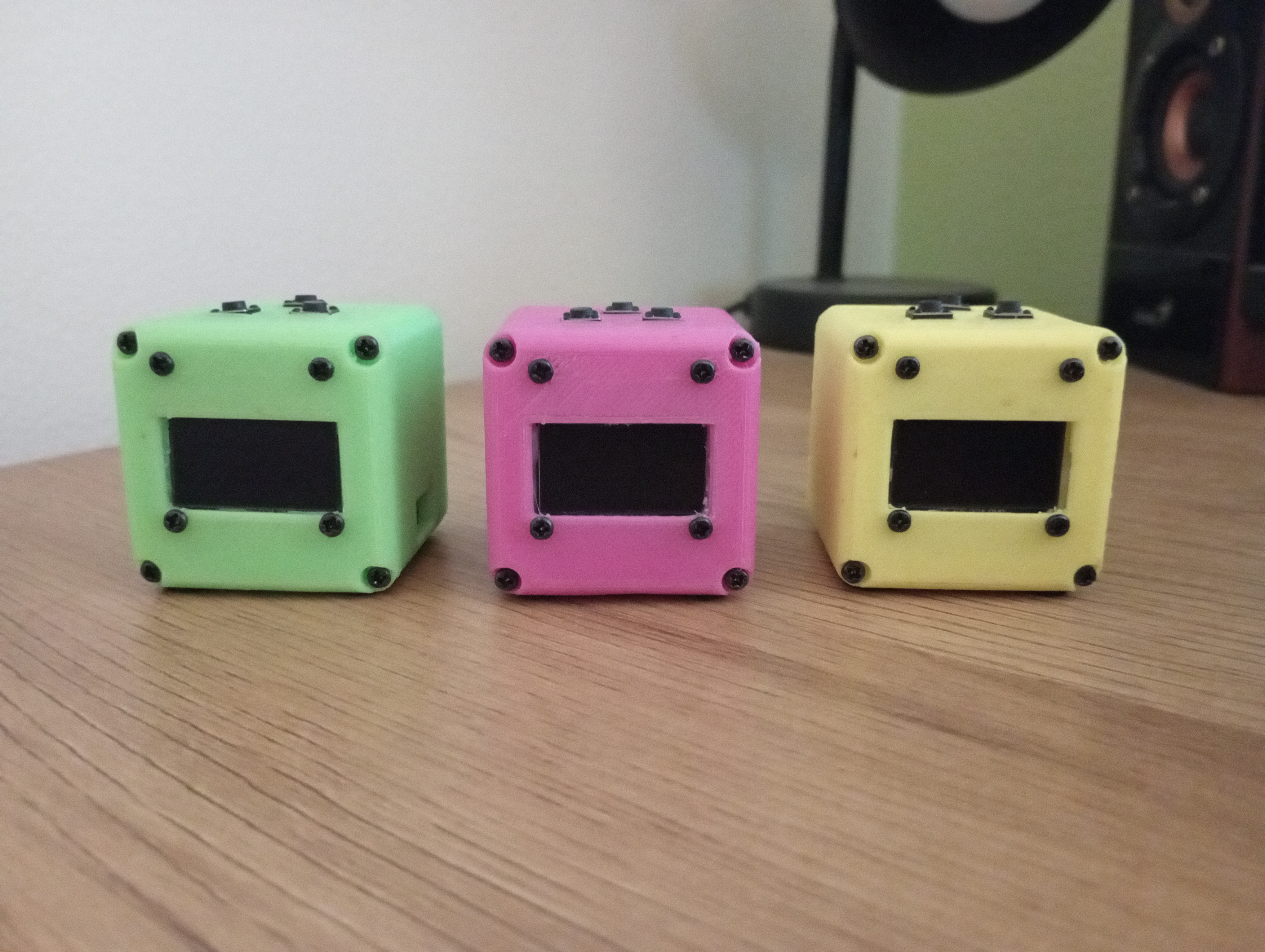
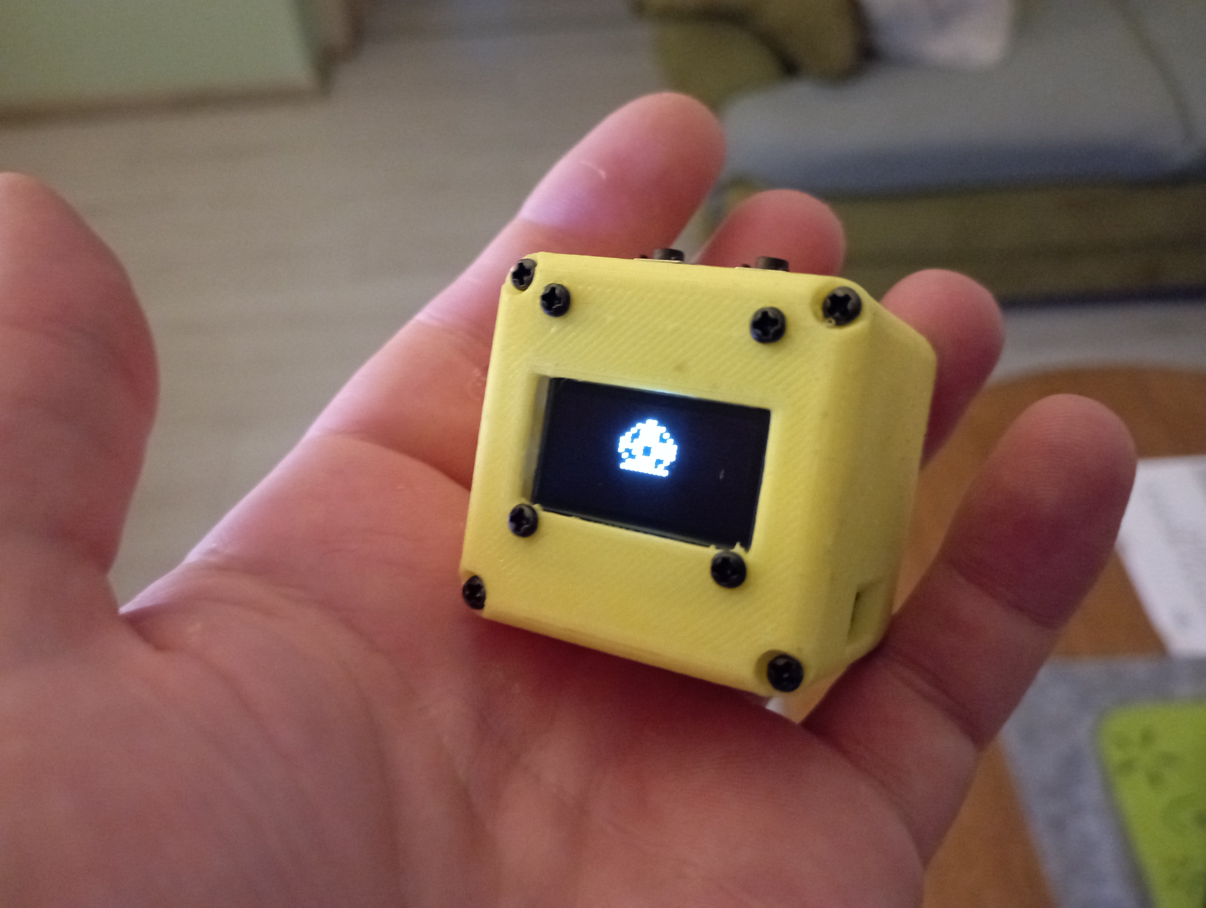
**SmartCube** is a tiny and customizable desk toy using the ESP8266 D1 Mini.
|
|
Built entirely from cheap, easy-to-find parts, it can connect to Wi-Fi and can be programmed to do just about anything:
|
|
show notifications, display the weather, monitor stuff, show a clock, serve a web site, be a virtual pet or whatever else your caffeine-fueled brain can imagine.
|
|
|
|
|
|
|
|
---
|
|
|
|
## Info
|
|
- **This is a hobby project I work on and develop for when I have literally nothing else to do, do not expect regular updates. You are free to clone this and do whatever you like with it**
|
|
- **Code**: I have a few projects developed for the Cube. You can see the list [here on my Gitea](https://git.kopic.hr/tomislav?tab=repositories&q=cube&sort=recentupdate)
|
|
- **V2**: There is also a more [powerful version](https://git.kopic.hr/tomislav/SmartCubeV2), it's pretty much the same but with extra features and is using ESP32, I only made one of them and I don't like it yet, it needs work.
|
|
- **Case**: 3D-printable design included in `/hardware` directory
|
|
- **Schematics**: and assembly instructions are also in the `/hardware` directory
|
|
|
|
---
|
|
|
|
## Bill of Materials
|
|
|
|
| **Component** | **Quantity** | **Description** | **Notes** |
|
|
|---------------------------|--------------|-------------------------------------------|---------------------------------------------|
|
|
| ESP8266 D1 Mini | 1 | Microcontroller module | |
|
|
| SSD1306 OLED Display | 1 | 128x64 resolution, I2C interface | |
|
|
| 14250 Rechargeable Battery| 1 | Lithium-ion battery | Make sure you get the rechargeable type, most 14250 are not |
|
|
| TP4056 Module | 1 | Charging and protection circuit | Does not need to have a USB connector |
|
|
| Push Buttons | 3 or 4 | Tactile push buttons | |
|
|
| Piezo Buzzer | 1 | 20mm buzzer for audio feedback | |
|
|
| Resistors (10kΩ) | 3 or 4 | Pull-down resistors for buttons | Not reqired if you are using ESP32 |
|
|
| Wires | Several | For connections | |
|
|
| Enclosure | 1 | 3D-printed or custom-made case | 3D printable STL files are in `hardware/case/` |
|
|
| 2x6mm screw | 12 | Small screws for seembling the case | Does not have to be exactly 6mm long |
|
|
|
|
---
|
|
|
|
## Demo Code Explanation
|
|
|
|
This repository contains a basic "Hello, World!" project for the SmartCube.
|
|
|
|
### Getting Started:
|
|
|
|
1. Download and install **[VSCode](https://code.visualstudio.com/)** or **[VSCodium](https://vscodium.com/)**.
|
|
2. Install the **[PlatformIO IDE extension](https://platformio.org/platformio-ide)**.
|
|
3. Clone this repository and open the project folder in VSCode/VSCodium.
|
|
4. PlatformIO will automatically handle environment setup and dependencies when you open the project.
|
|
|
|
### Project Structure:
|
|
|
|
All source code is located in the `src/` directory.
|
|
You should start by opening **`src/main.cpp`**, which contains the entry point and initialization logic.
|
|
|
|
### What the Code Does:
|
|
|
|
This demo handles basic system functionality, including:
|
|
|
|
* System initialization
|
|
* Button input handling
|
|
* OLED display output configuration
|
|
* WiFi management
|
|
|
|
### Key Features
|
|
|
|
1. **WiFi Management**:
|
|
- The [cubeWifiManager](https://git.kopic.hr/tomislav/SmartCubeV1/src/branch/main/src/SmartCube/cubeWifiManager.h) class manages WiFi connectivity seamlessly.
|
|
- If no known WiFi network is available, it starts a configuration portal and creates an access point (AP), allowing users to connect the SmartCube to a network from another WiFi-enabled device.
|
|
- The OLED display shows the access point details, such as the AP name and IP address, making the setup process very easy.
|
|
|
|
2. **Button Handling**:
|
|
- Buttons are mapped to specific GPIO pins: `PIN_BTN_L` (Left), `PIN_BTN_M` (Middle), and `PIN_BTN_R` (Right).
|
|
- The [cubeButtonHandler](https://git.kopic.hr/tomislav/SmartCubeV1/src/branch/main/src/SmartCube/cubeButtons.h) function, executed in the [loop()](https://git.kopic.hr/tomislav/SmartCubeV1/src/commit/1cb51f502d92a91c6a83ce6364b434db31bfd864/src/main.cpp#L47), monitors and interprets button presses, differentiating between short and long presses.
|
|
|
|
#### Default Button Actions
|
|
- **Right Button**:
|
|
- *Short Press*: Turns the OLED display **on** (if previously off).
|
|
- *Long Press*: Turns the OLED display **off**, helping conserve power.
|
|
|
|
- **Left + Middle Buttons (Simultaneous Long Press)**:
|
|
- Triggers an ESP8266 reboot, effectively restarting the device.
|
|
|
|
This is meant to provide a minimal starting point for further development with the SmartCube.
|
|
|
|
---
|
|
|
|
## Assembly Instructions
|
|
|
|
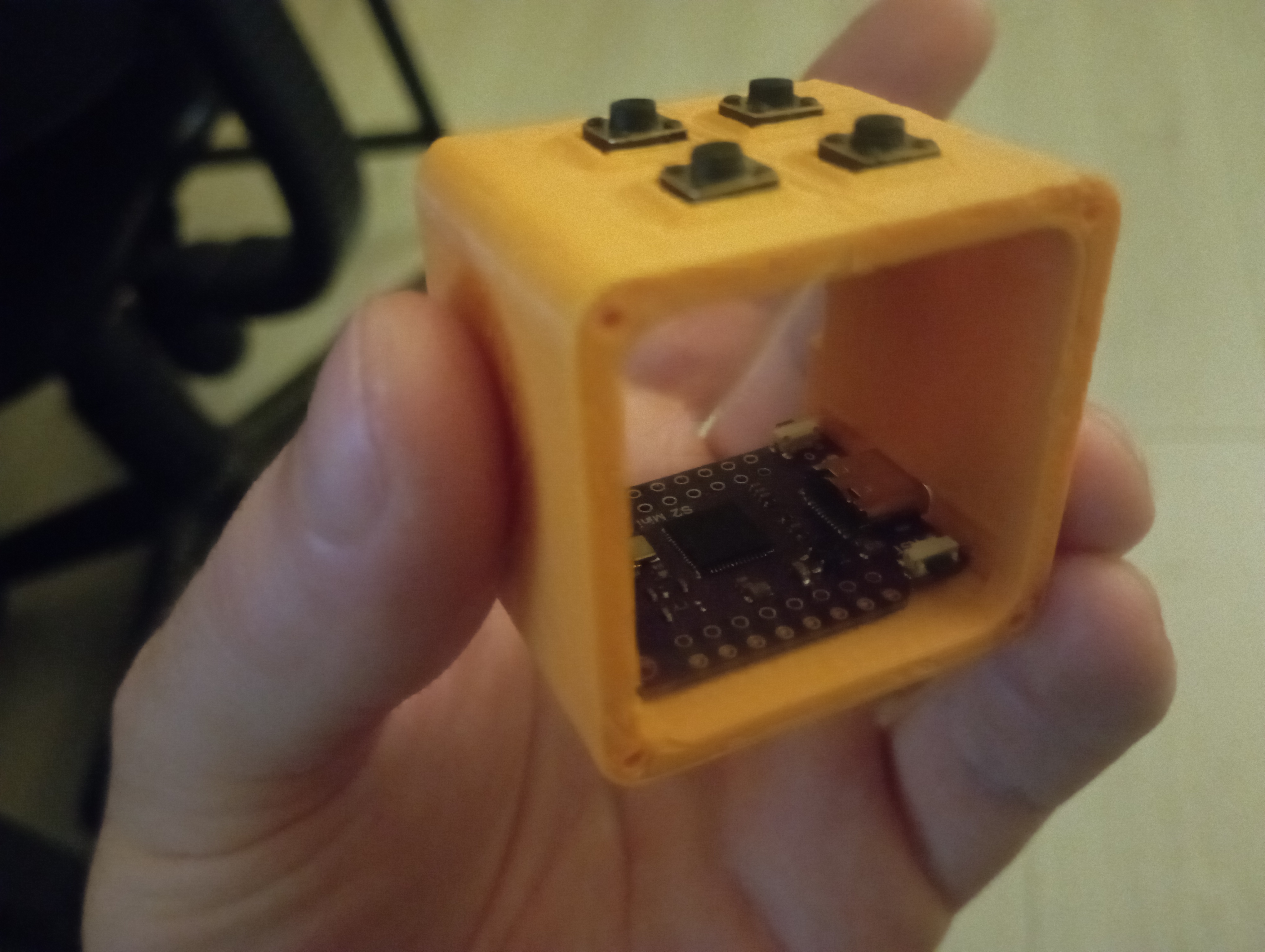
1. Push the ESP8266 or ESP32 microcontroller in the ledge on the bottom [the cube body](https://git.kopic.hr/tomislav/SmartCubeV1/raw/branch/main/hardware/case/SmartCube_Body_3_button.stl) with the USB-C port facing the hole.
|
|
Body with 3 or 4 button slots is available in the `hardware/case/`
|
|
|
|
2. **Buttons**: You can also glue in the buttons to the top slots at this step
|
|
|
|
|
|
|
|
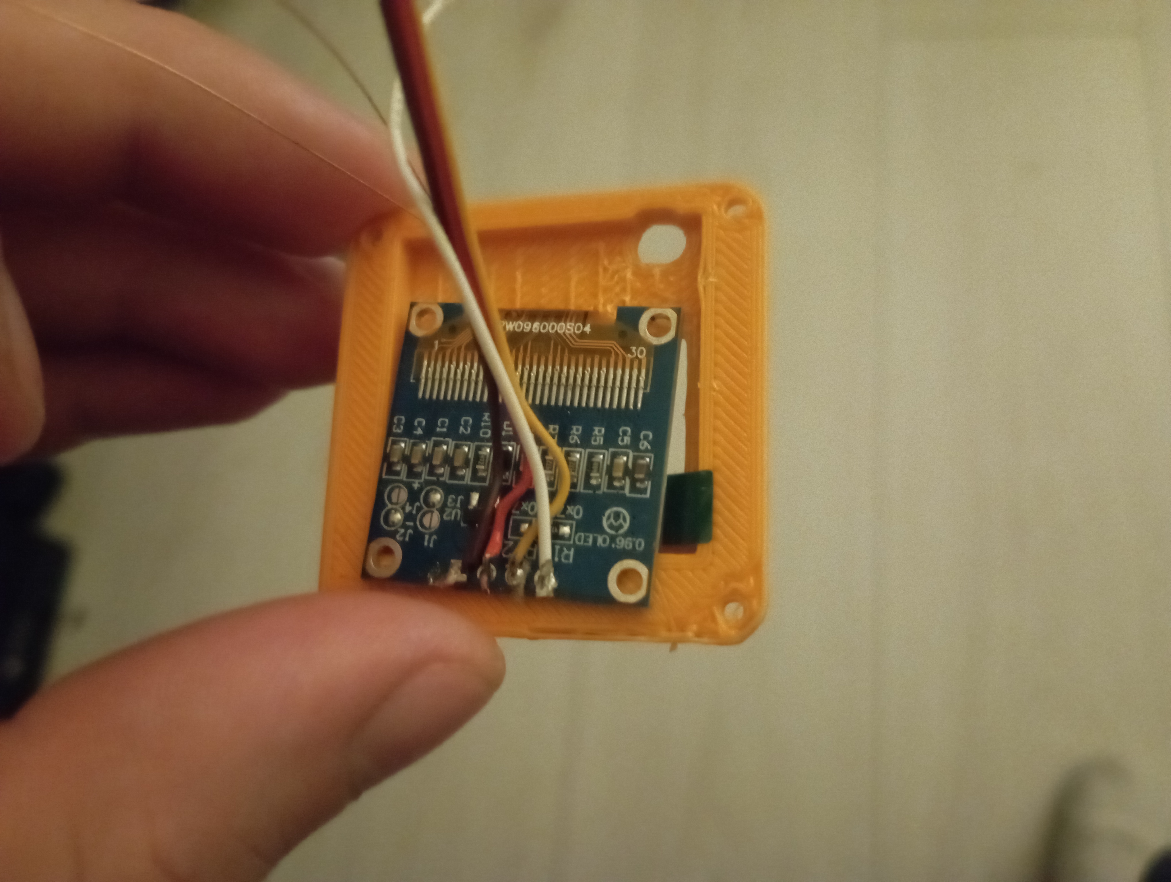
3. **OLED Display**: Crew in or glue the SSD1306 to the [front part of the cube](https://git.kopic.hr/tomislav/SmartCubeV1/raw/branch/main/hardware/case/SmartCube_Front.stl) solder the wires to the OLED
|
|
|
|
|
|
|
|
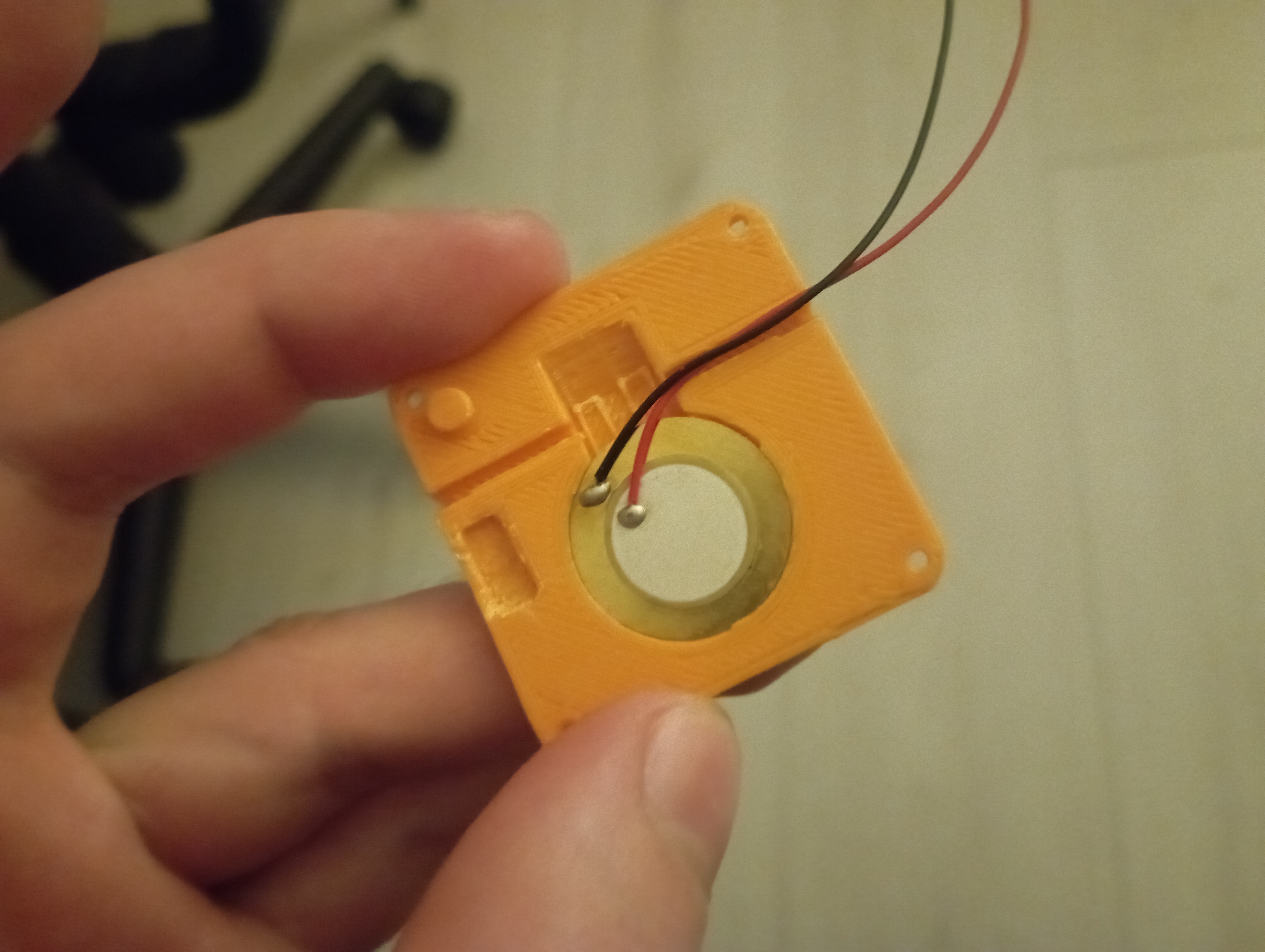
4. **Buzzer**: Glue in the buzzer to the [back part of the cube](https://git.kopic.hr/tomislav/SmartCubeV1/raw/branch/main/hardware/case/SmartCube_Back_Speaker_Side_Hole.stl)
|
|
|
|
|
|
|
|
5. Solder all of the components to the microcontroller:
|
|
## Pin Connections
|
|
|
|
Pin numbers for buttons and other stuff is defined in the [example config](https://git.kopic.hr/tomislav/SmartCubeV1/src/branch/main/src/example_config.h) and the schematic for the [D1 Mini is here](https://git.kopic.hr/tomislav/SmartCubeV1/raw/branch/main/hardware/schematics/esp8266.png):
|
|
You don't have to follow my pin definition exactly but I find this the easiest way to assemble and fit everything in. 3 Button variant is the standard. If you are gonna go with the 4 button variant you will need to define this yourself.
|
|
|
|
- Button Left (PIN_BTN_L): GPIO12
|
|
- Button Middle (PIN_BTN_M): GPIO13
|
|
- Button Right (PIN_BTN_R): GPIO15
|
|
- Piezo Buzzer (PIN_BUZZER): GPIO0
|
|
|
|
The OLED display must to be connected via I2C on pins:
|
|
- **SDA**: D2 (GPIO4)
|
|
- **SCL**: D1 (GPIO5)
|
|
- **GND**: GND
|
|
- **VCC**: 3.3V pin or directly to the TP4056 output
|
|
|
|
6. **Power Supply Setup**:
|
|
- Solder the 14250 battery to the TP4056 module input pins.
|
|
- Wire the output of the TP4056 to the **3.3V pin** on the D1 Mini to power the device.
|
|
- Connect the **5V output pin** from the D1 Mini to the **input port** on the TP4056 module to allow charging trough the Data USB port on the ESP8266.
|
|
|
|

|
|
|
|
---
|
|
|
|
## Notes
|
|
|
|
- This is still a work in progress
|
|
- Everything is pretty tightly packed in there and it's a mess. But it's not as hard to make as it looks.
|
|

|
|
|
|
- Ensure all connections are secure. Hot glue is your friend.
|
|
- Test the circuit thoroughly before placing and glueing it in the enclosure.
|
|
- Battery is the trickiest part to fit in, it's best to glue the charging module directly to it and put it in the case last
|
|
|
|
|
|
For questions or additional details, feel free to reach out! I would love to hear some feedback.
|
|
Good luck and have fun :)
|
|
|
|
|