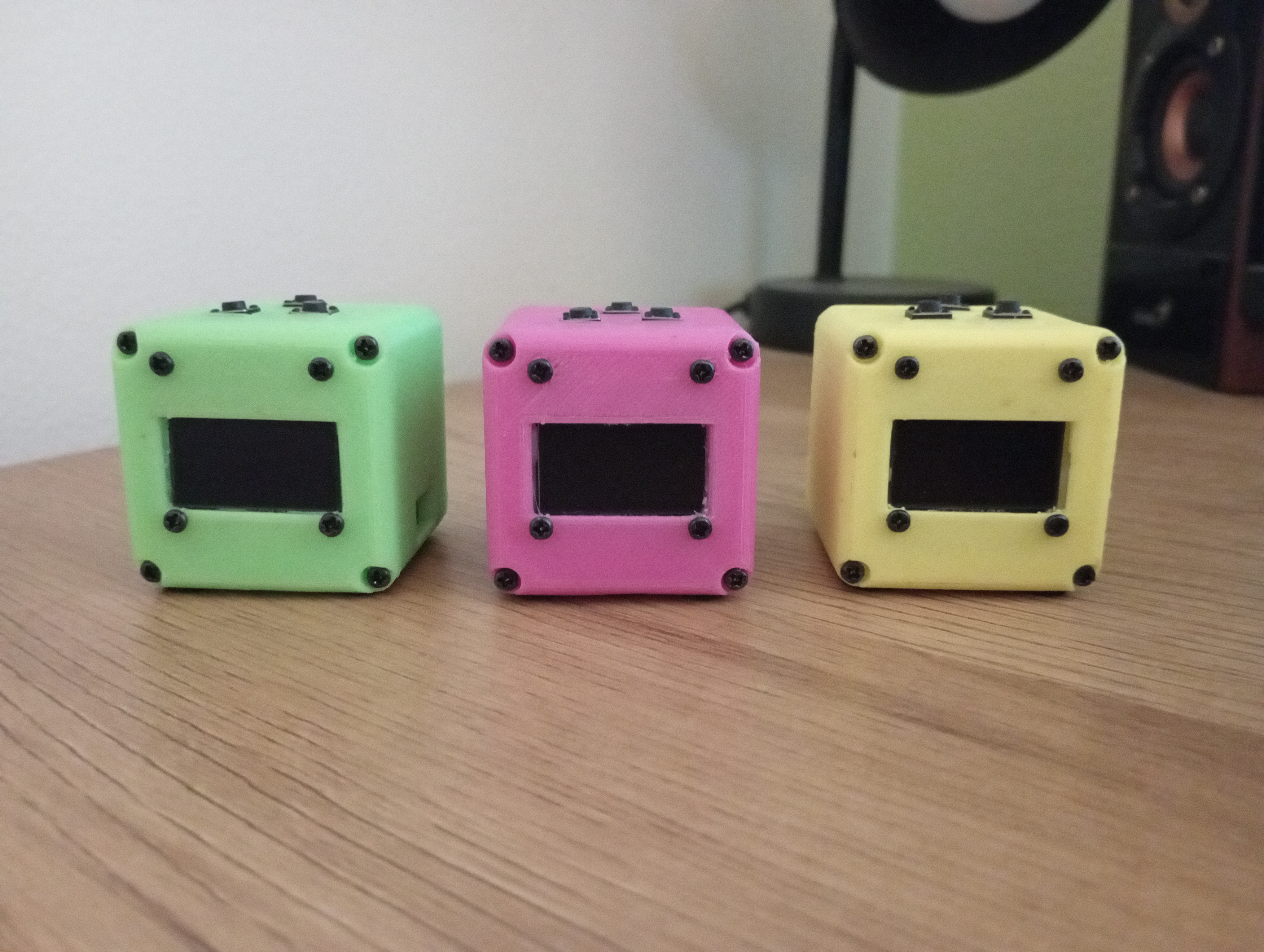
SmartCube
SmartCube is a tinly and customizable desk toy using the ESP8266 D1 Mini. It features a rechargeable power supply, three input buttons, an SSD1306 OLED display and a 20mm piezo buzzer for sound.
Info
- Code: I have a few projects developed for the cube. You can see the list here on my Gitea
- Case: 3D-printable design included in
/hardwaredirectory - Schematics: and assembly instructions are also in the
/hardwaredirectory
Bill of Materials
| Component | Quantity | Description | Notes |
|---|---|---|---|
| ESP8266 D1 Mini | 1 | Microcontroller module | |
| SSD1306 OLED Display | 1 | 128x64 resolution, I2C interface | |
| 14250 Rechargeable Battery | 1 | Lithium-ion battery | Make sure you get the rechargeable type, most 14250 are not |
| TP4056 Module | 1 | Charging and protection circuit | Does not need to have a USB connector |
| Push Buttons | 3 | Tactile push buttons | |
| Piezo Buzzer | 1 | Buzzer for audio feedback | |
| Resistors (10kΩ) | 3 | Pull-down resistors for buttons | Ensures stable button input |
| Wires | Several | For connections | |
| Enclosure | 1 | 3D-printed or custom-made case | 3D printable STL files are in hardware/case/ |
| 2x6mm screw | 12 | Small screws for seembling the case | Does not have to be exactly 6mm long |
Demo Code Explanation
The provided demo code is the starting point(hello world) for the SmartCube development with Platform.io, it does the basic system initialization, button handling, OLED display output configured, and WiFi management:
Key Features
-
WiFi Management:
- The
cubeWifiManagerclass manages WiFi connectivity seamlessly. - If no known WiFi network is available, it starts a configuration portal and creates an access point (AP), allowing users to connect the SmartCube to a network from another WiFi-enabled device.
- The OLED display shows the access point details, such as the AP name and IP address, making the setup process very easy.
- The
-
Button Handling:
- Buttons are mapped to specific GPIO pins:
PIN_BTN_L(Left),PIN_BTN_M(Middle), andPIN_BTN_R(Right). - The
cubeButtonHandler()function, executed in theloop(), monitors and interprets button presses, differentiating between short and long presses.
- Buttons are mapped to specific GPIO pins:
Default Button Actions
-
Right Button:
- Short Press: Turns the OLED display on (if previously off).
- Long Press: Turns the OLED display off, helping conserve power.
-
Left + Middle Buttons (Simultaneous Long Press):
- Triggers an ESP8266 reboot, effectively restarting the device.
Pin Connections
OLED Display Settings
#define SCREEN_WIDTH 128
#define SCREEN_HEIGHT 64
#define OLED_RESET -1
#define FRAMERATE 8
The OLED display is connected via I2C to the D1 Mini:
- SDA: D2 (GPIO4)
- SCL: D1 (GPIO5)
Buttons and Buzzer
#define PIN_BTN_L 12 // D6
#define PIN_BTN_M 13 // D7
#define PIN_BTN_R 15 // D8
#define PIN_BUZZER 0 // D3
- Button Left (PIN_BTN_L): GPIO12
- Button Middle (PIN_BTN_M): GPIO13
- Button Right (PIN_BTN_R): GPIO15
- Piezo Buzzer (PIN_BUZZER): GPIO0
Assembly Instructions
-
Power Supply Setup:
- Solder the 14250 battery to the TP4056 module input pins.
- Wire the output of the TP4056 to the 3.3V pin on the D1 Mini to power the device.
- Connect the 5V output pin from the D1 Mini to the input port on the TP4056 module to allow charging trough the Data USB port on the ESP8266.

-
OLED Display: Solder connections for SDA (D2, GPIO4) and SCL (D1, GPIO5) to the respective pins on the D1 Mini.
-
Buttons: Attach each button to the specified GPIO pins with pull-down resistors to ensure reliable input.
-
Buzzer: Connect the piezo buzzer, negative to the GPI00, positive to 3.3v
-
Enclosure: Assemble all components in a secure housing. May require some hot glue to keep components in
Notes
-
This is still a work in progress
-
Everything is pretty tightly packed in there and it's a mess. But it's not as hard to make as it looks.

-
Ensure all connections are secure. Hot glue is your friend.
-
Test the circuit thoroughly before placing and glueing it in the enclosure.
-
Battery is the trickiest part to fit in, it's best to glue the charging module directly to it and put it in the case last
For questions or additional details, feel free to reach out!