11 KiB
SmartCube
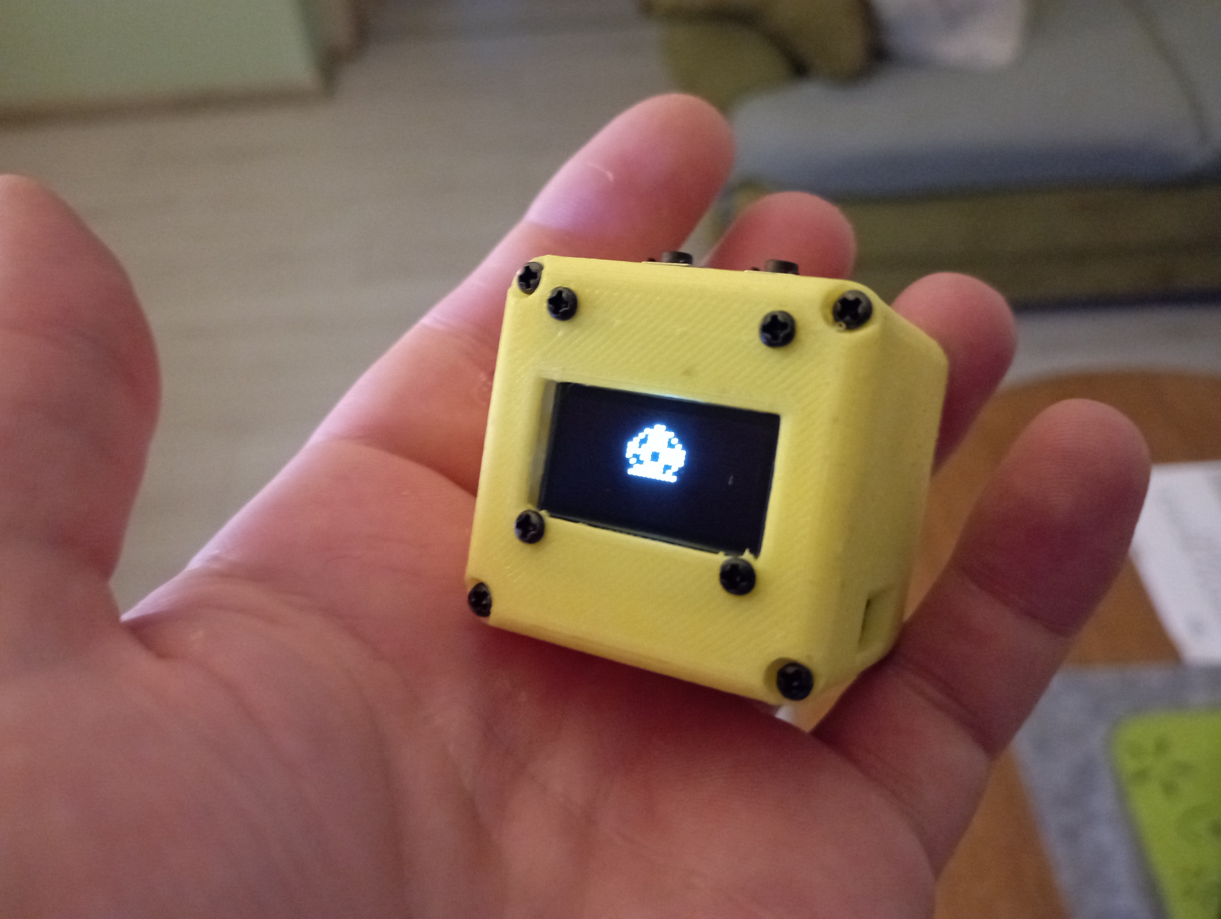
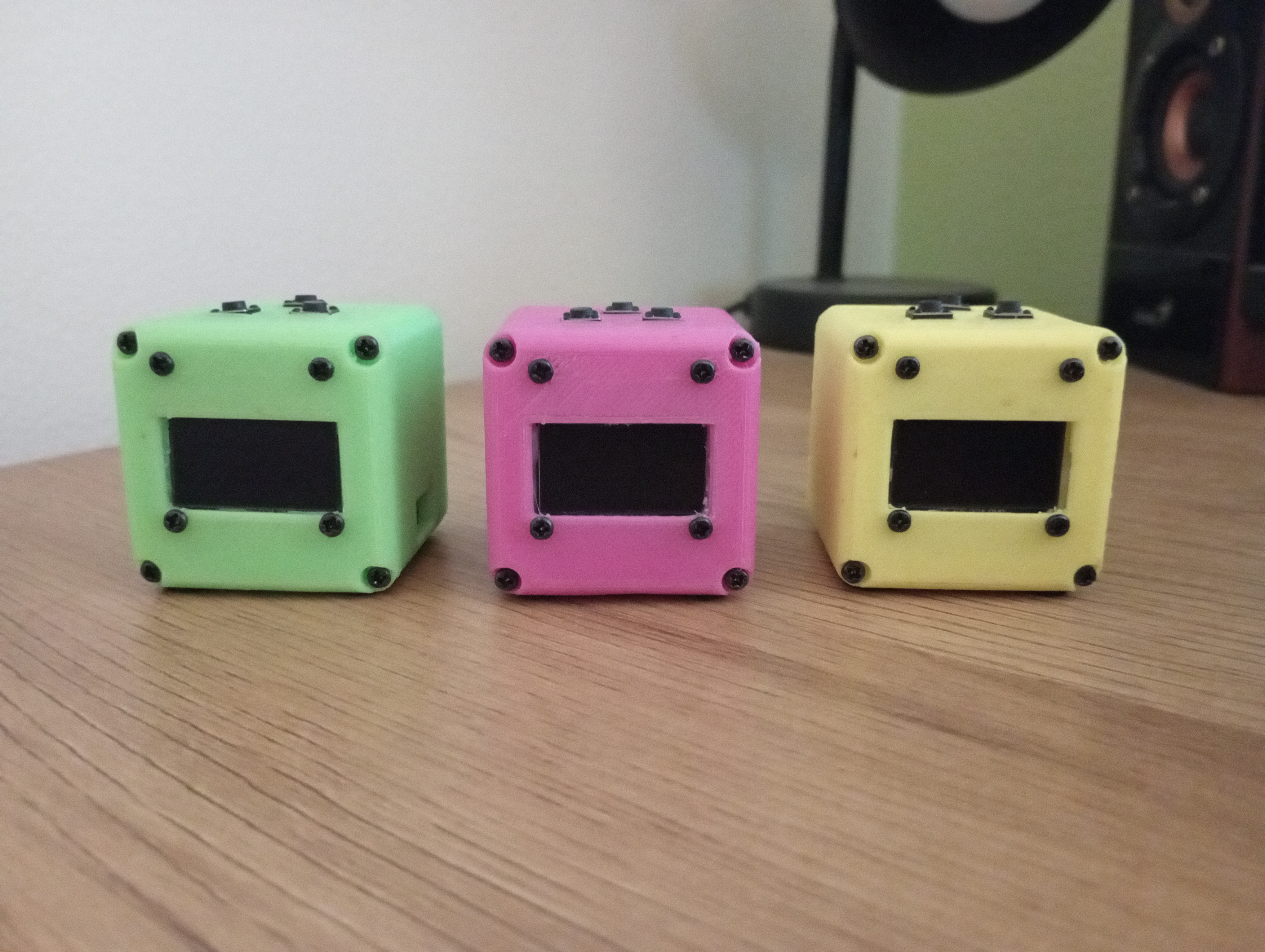
SmartCube is a tiny and customizable desk toy using the ESP8266 D1 Mini. Built entirely from cheap, easy-to-find parts, it can connect to Wi-Fi and can be programmed to do just about anything: show notifications, display the weather, monitor stuff, show a clock, serve a web site, mine crypto, be a virtual pet or whatever else your caffeine-fueled brain can imagine.
Info
- This is a hobby project I work on and develop for when I have literally nothing else to do, do not expect regular updates. You are free to clone this and do whatever you like with it
- Code: I have a few projects developed for the Cube. You can see the list here on my Gitea
- V2: There is also a more powerful version, it's pretty much the same but with extra features and is using ESP32, I only made one of them and I don't like it yet, it needs work.
- Case: 3D-printable design included in
/hardwaredirectory - Schematics: and assembly instructions are also in the
/hardwaredirectory
Demo Code Explanation
This repository contains a basic "Hello, World!" project for the SmartCube.
Getting Started:
- Download and install VSCode or VSCodium.
- Install the PlatformIO IDE extension.
- Clone this repository and open the project folder in VSCode/VSCodium.
- PlatformIO will automatically handle environment setup and dependencies when you open the project.
Project Structure:
All source code is located in the src/ directory.
You should start by opening src/main.cpp, which contains the entry point and initialization logic.
What the Code Does:
This demo handles basic system functionality, including:
- System initialization
- Button input handling
- OLED display output configuration
- WiFi management
Key Features
-
WiFi Management:
- The cubeWifiManager class manages WiFi connectivity seamlessly.
- If no known WiFi network is available, it starts a configuration portal and creates an access point (AP), allowing users to connect the SmartCube to a network from another WiFi-enabled device.
- The OLED display shows the access point details, such as the AP name and IP address, making the setup process very easy.
-
Button Handling:
- Buttons are mapped to specific GPIO pins:
PIN_BTN_L(Left),PIN_BTN_M(Middle), andPIN_BTN_R(Right). - The cubeButtonHandler function, executed in the loop(), monitors and interprets button presses, differentiating between short and long presses.
- Buttons are mapped to specific GPIO pins:
Default Button Actions
-
Right Button:
- Short Press: Turns the OLED display on (if previously off).
- Long Press: Turns the OLED display off, helping conserve power.
-
Left + Middle Buttons (Simultaneous Long Press):
- Triggers an ESP8266 reboot, effectively restarting the device.
This is meant to provide a minimal starting point for further development with the SmartCube.
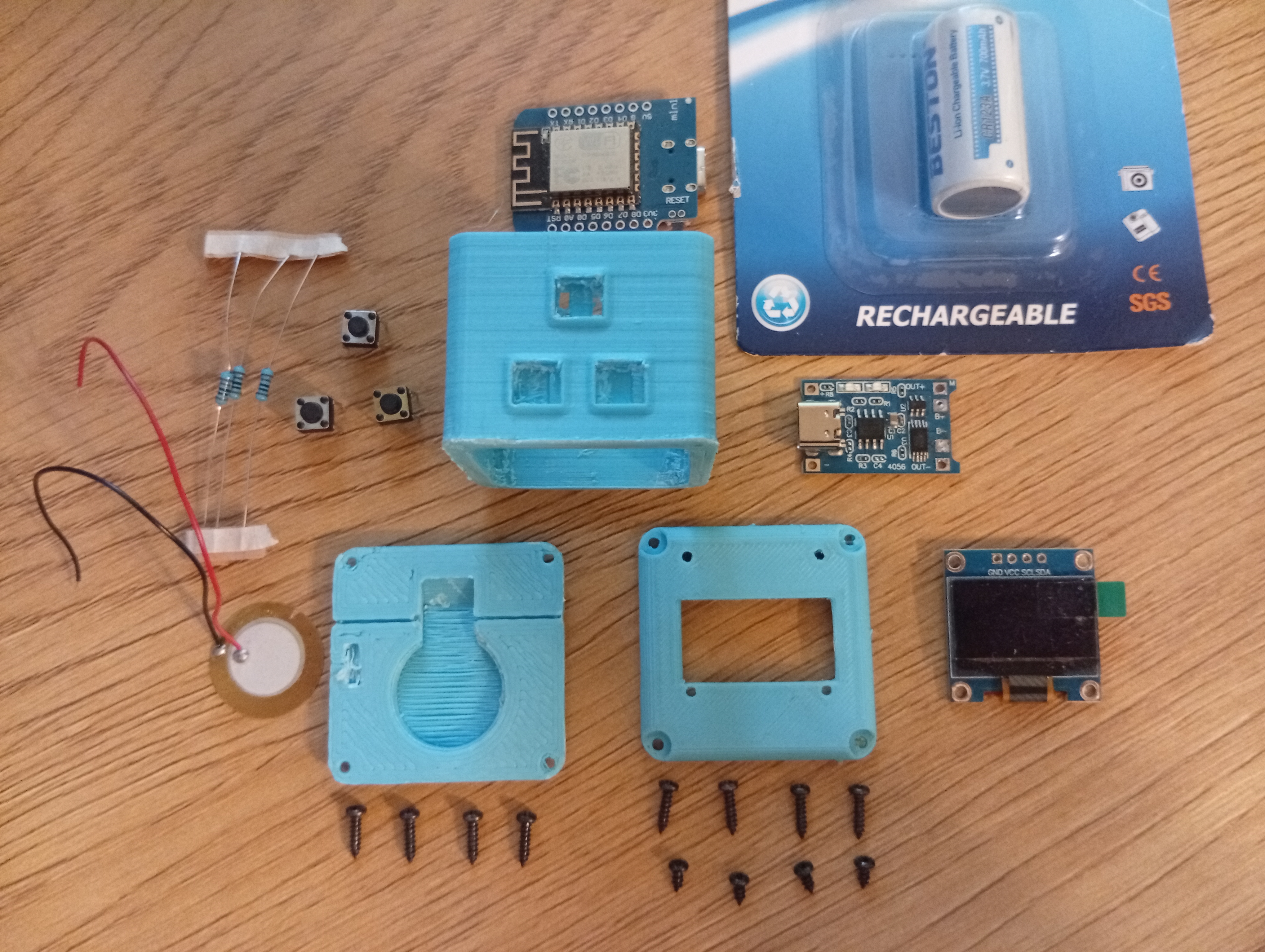
Bill of Materials
| Component | Quantity | Description | Notes |
|---|---|---|---|
| ESP8266 D1 Mini | 1 | Microcontroller module | |
| SSD1306 OLED Display | 1 | 128x64 resolution, I2C interface | |
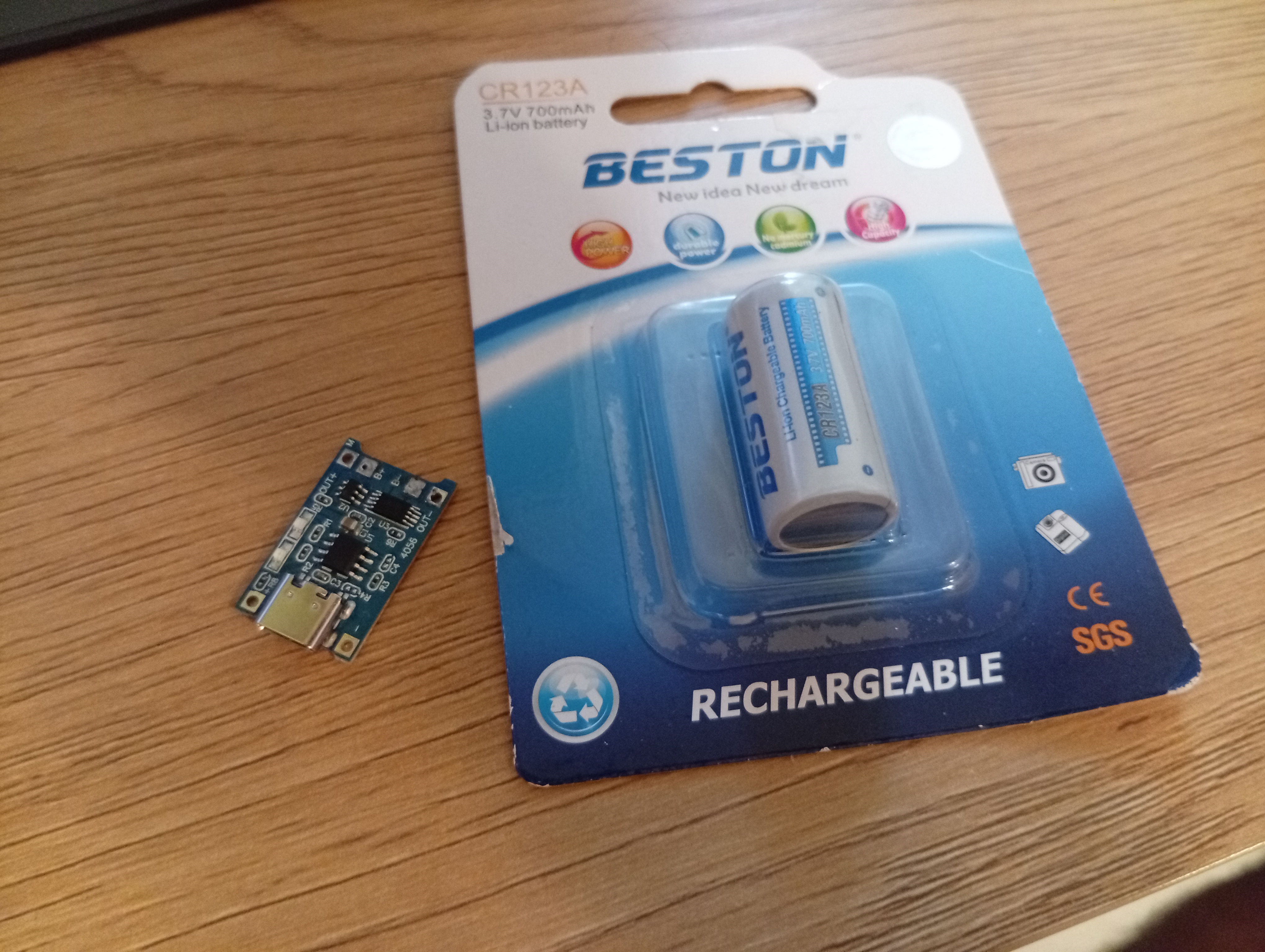
| 14250 Rechargeable Battery | 1 | Lithium-ion battery | Make sure you get the rechargeable type, most 14250 are not |
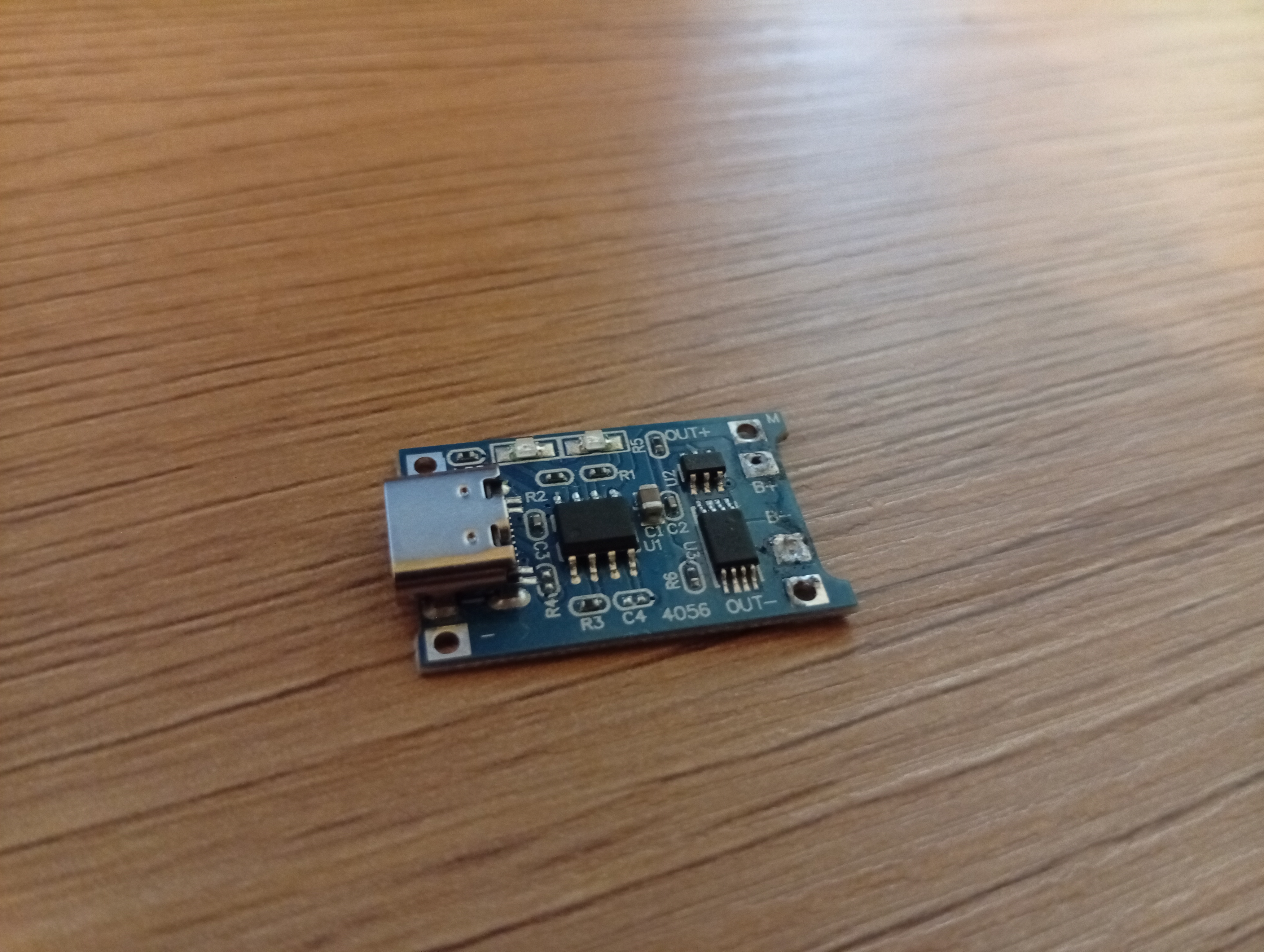
| TP4056 Module | 1 | Charging and protection circuit | Does not need to have a USB connector |
| 6x6 Push Buttons | 3 or 4 | Tactile push buttons | |
| 20mm Piezo Buzzer | 1 | Caseless buzzer for audio | |
| Resistors (10kΩ) | 3 or 4 | Pull-down resistors for buttons | |
| Wires | Several | Thin wires for connections | |
| Enclosure | 1 | 3D-printed case | 3D printable STL files are in hardware/case/ |
| 2x6mm screw | 8 | Small screws for assembling the case | Does not have to be exactly 6mm long |
| 2x2mm screw | 4 | Small screws for the front | Mostly for cosmetic purposes |
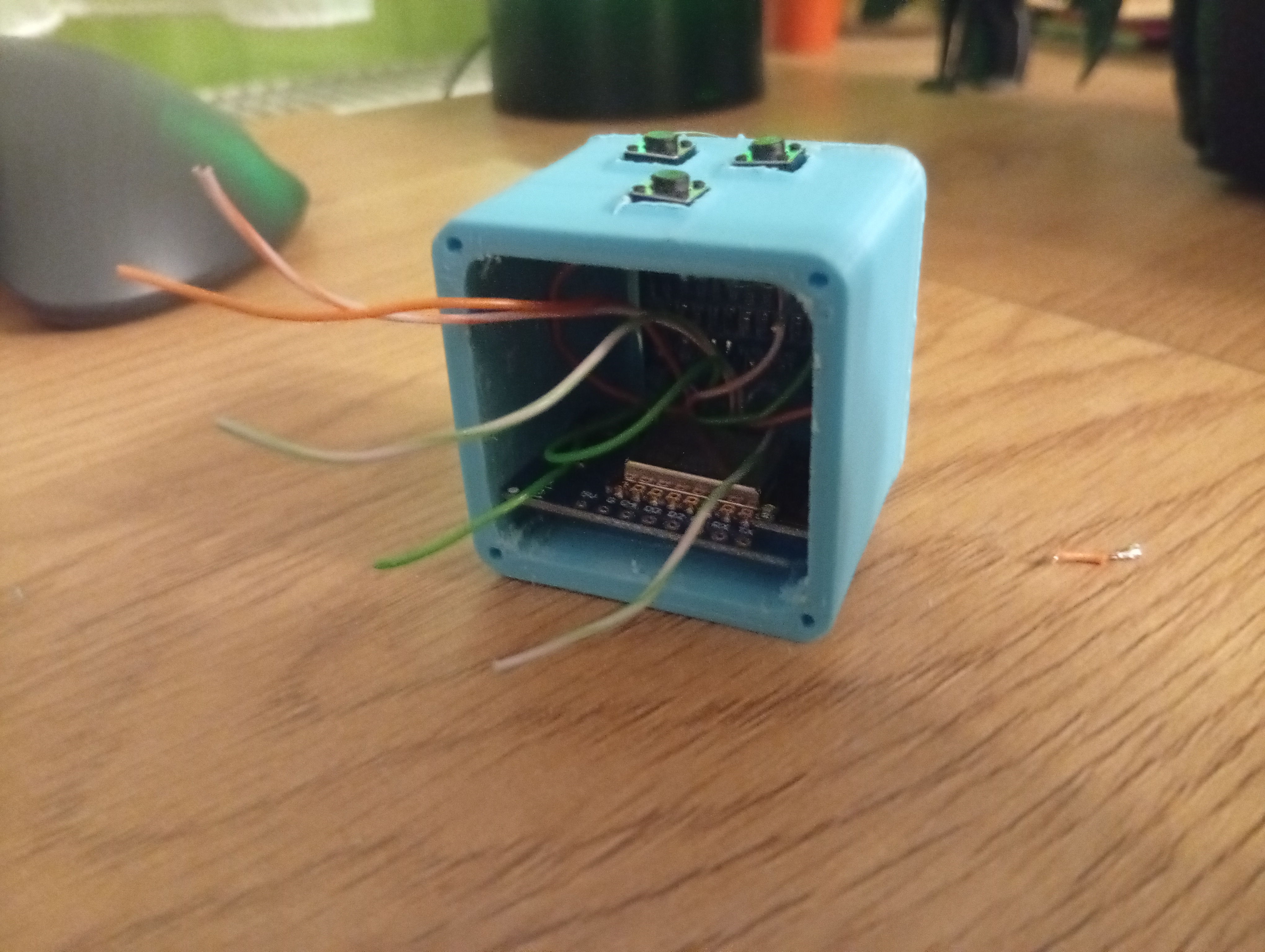
Assembly Instructions
- Body
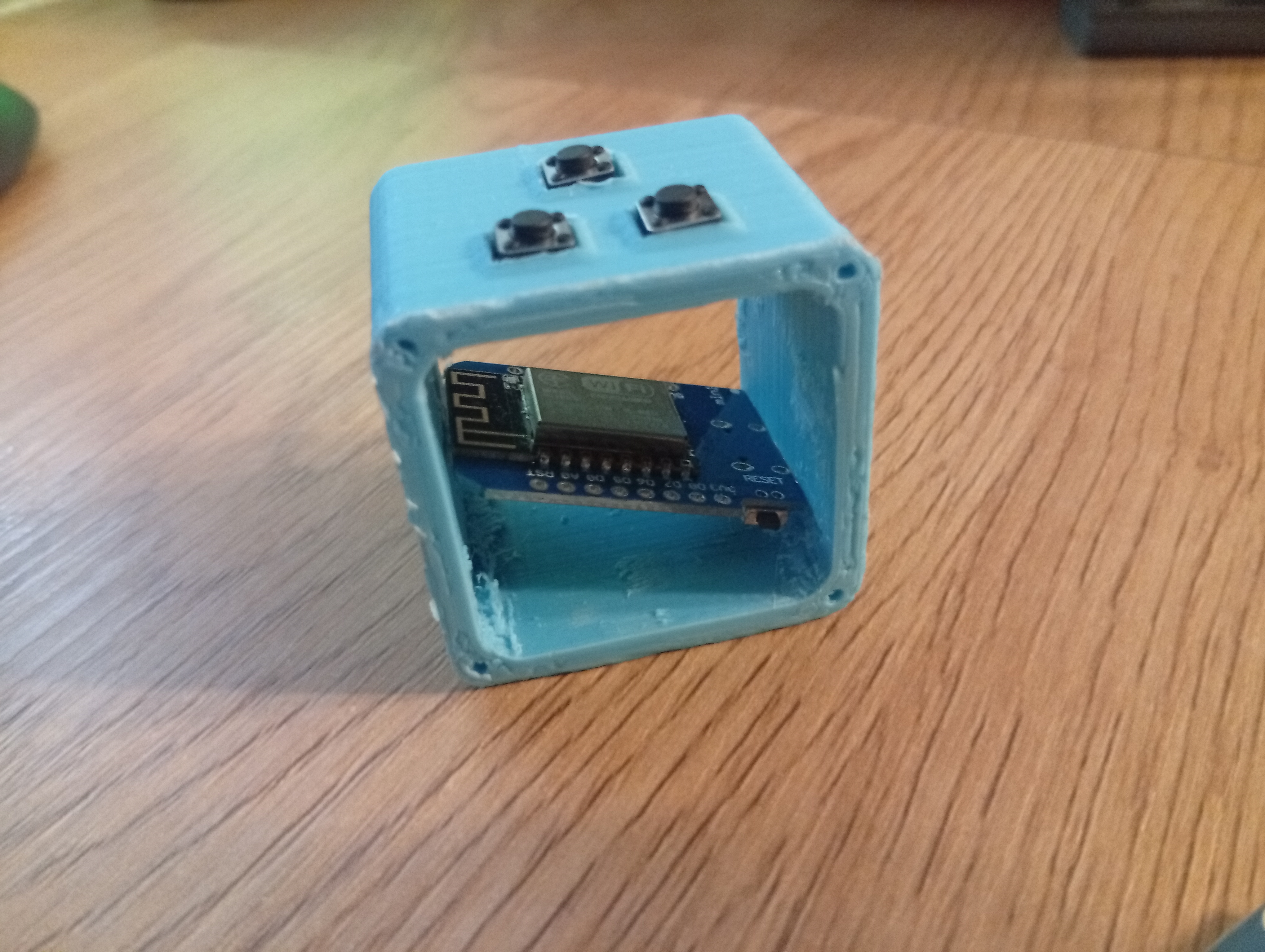
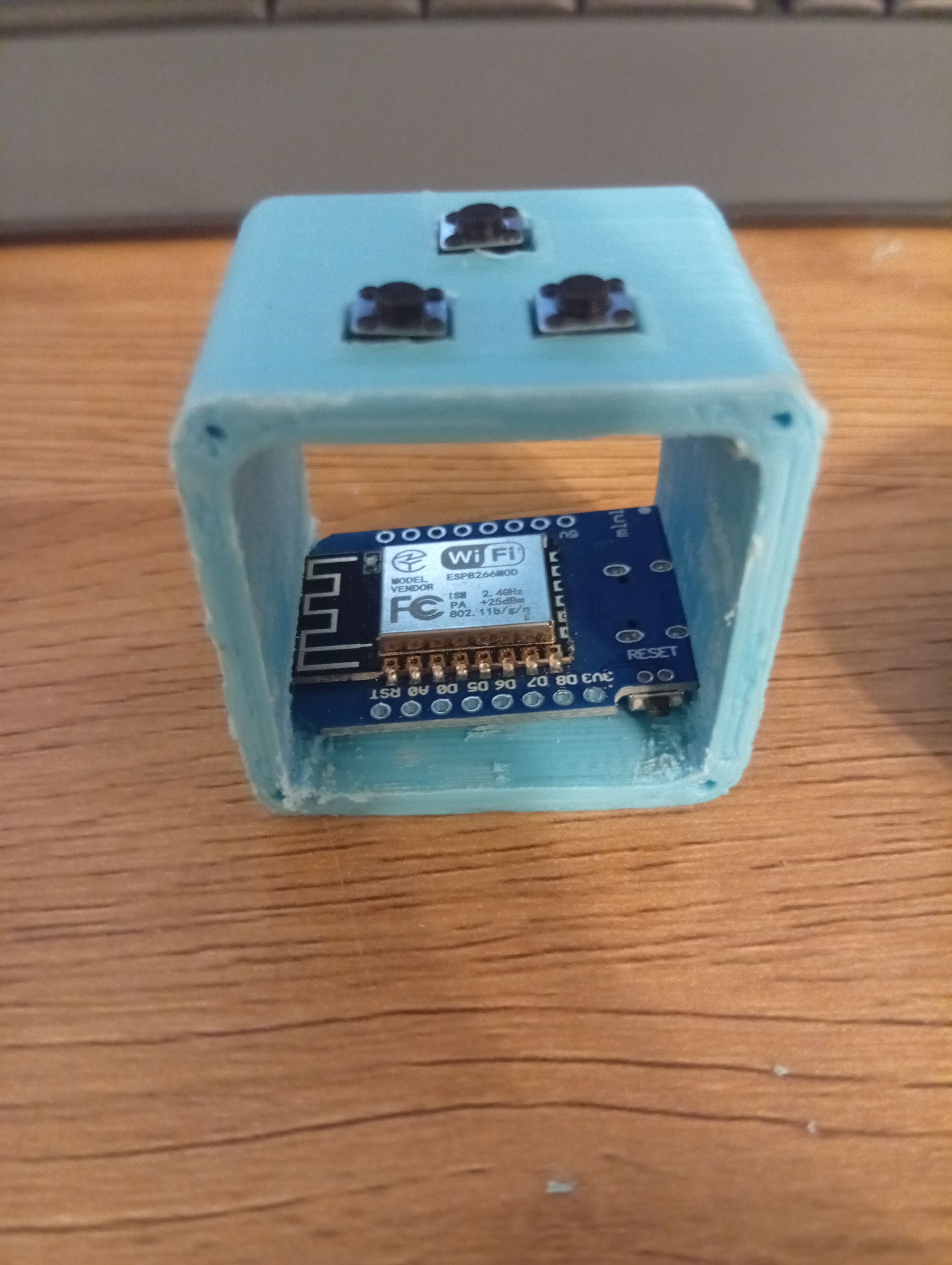
Push the ESP8266 microcontroller in the ledge on the bottom the cube body, it should 'click in' with the USB-C port facing the hole.
Body with 3 or 4 button slots is available in the hardware/case/
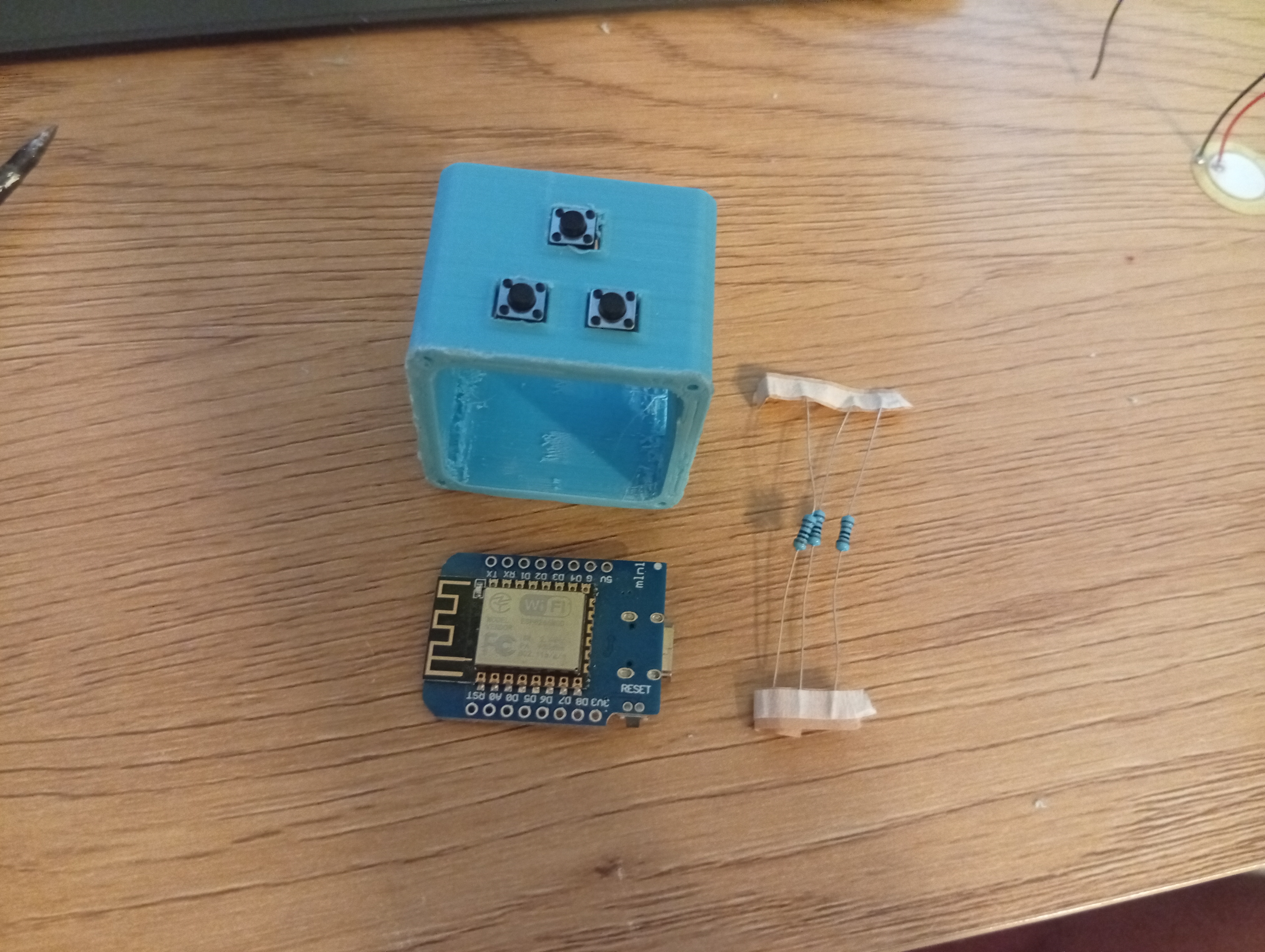
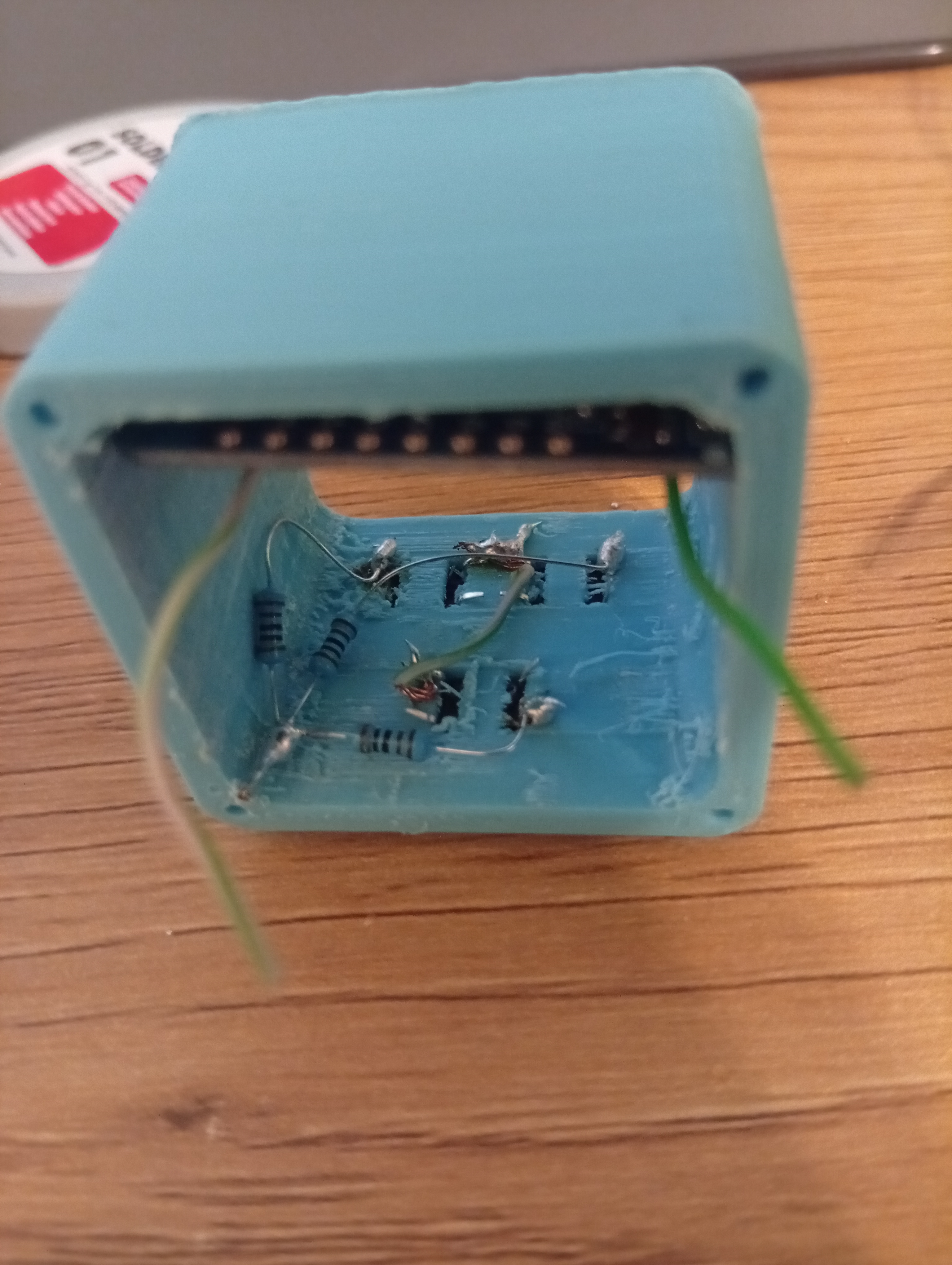
- Buttons
At this step, glue the buttons into the top slots and solder resistors to their outputs. You can connect the resistor outputs together, and don't forget to attach an extra wire to the button inputs, this will later be used to connect them to the 3.3V line.
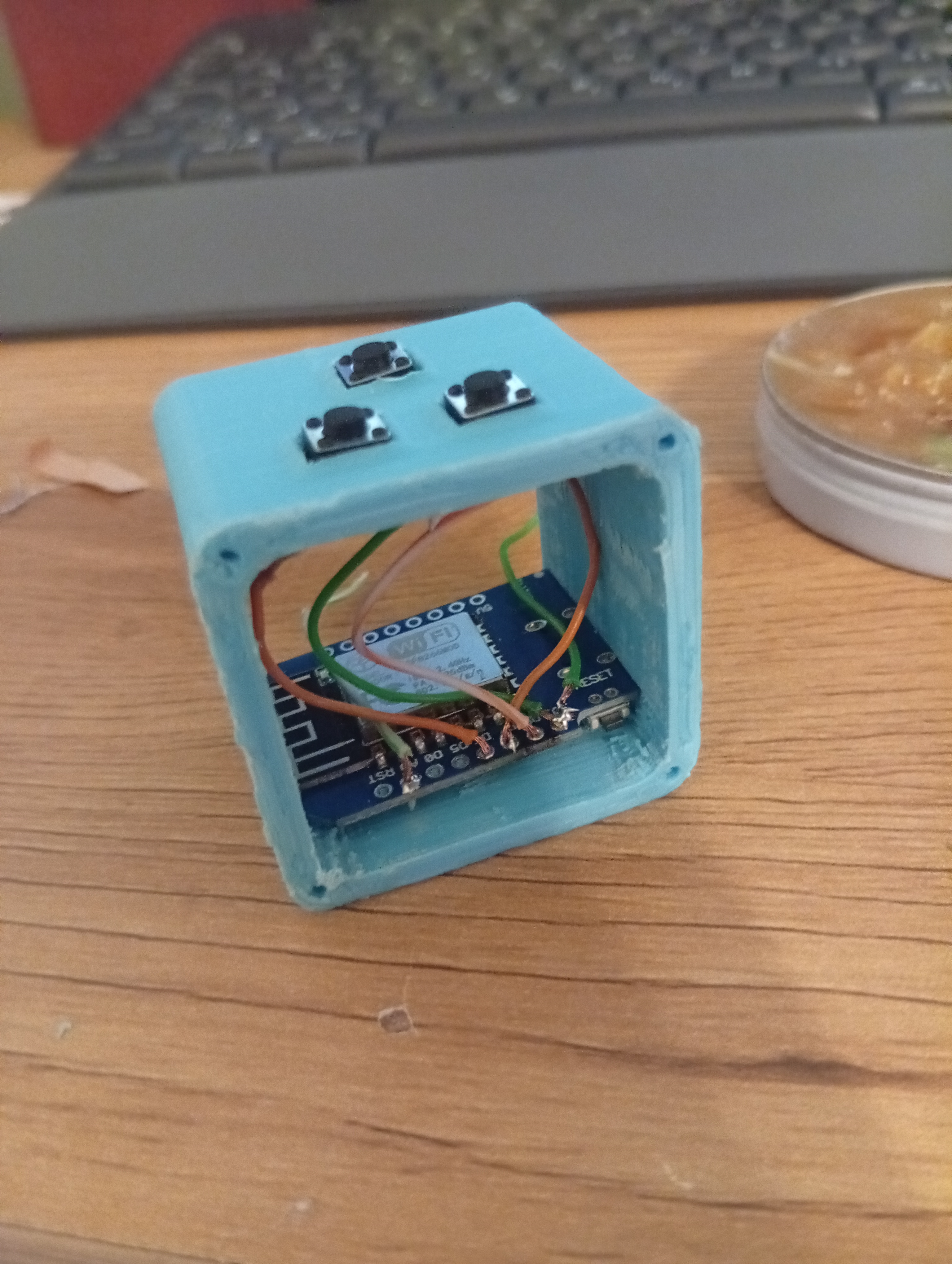
Next, solder all of the button outputs to the microcontroller.
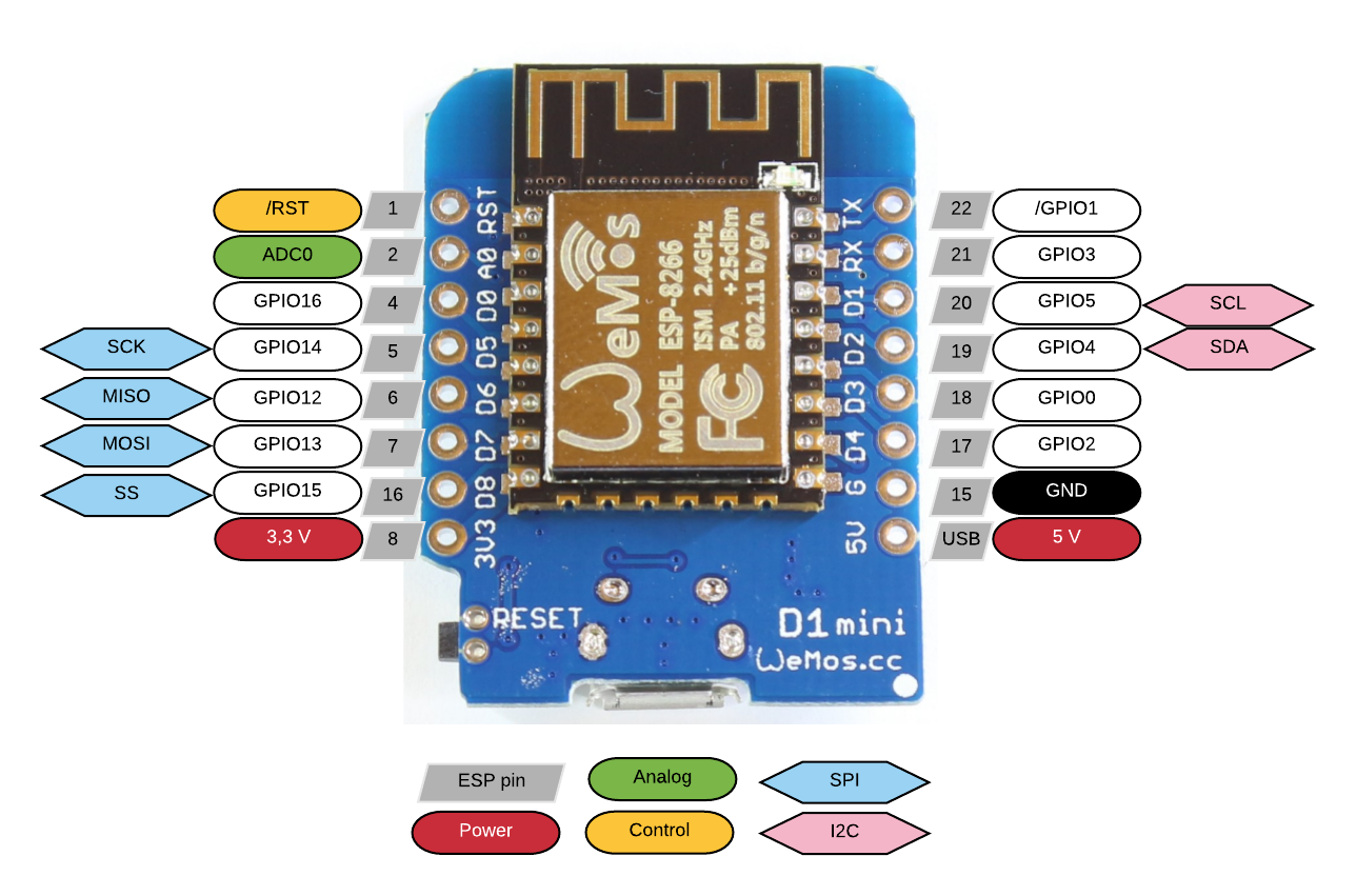
Pin numbers for the buttons (and other components) are defined in the example config, and the schematic for the D1 Mini is here. You don't have to follow my exact pin definitions, but I've found this setup to be the easiest way to assemble and fit everything in. The 3-button variant is the standard. If you decide to go with 4 buttons, you'll need to define the extra pin yourself in the code.
- Button Left (PIN_BTN_L): (D6) GPIO12
- Button Middle (PIN_BTN_M): (D7) GPIO13
- Button Right (PIN_BTN_R): (D8) GPIO15
Finally, solder the GND wire to the resistor outputs and connect 3.3V to the button inputs.
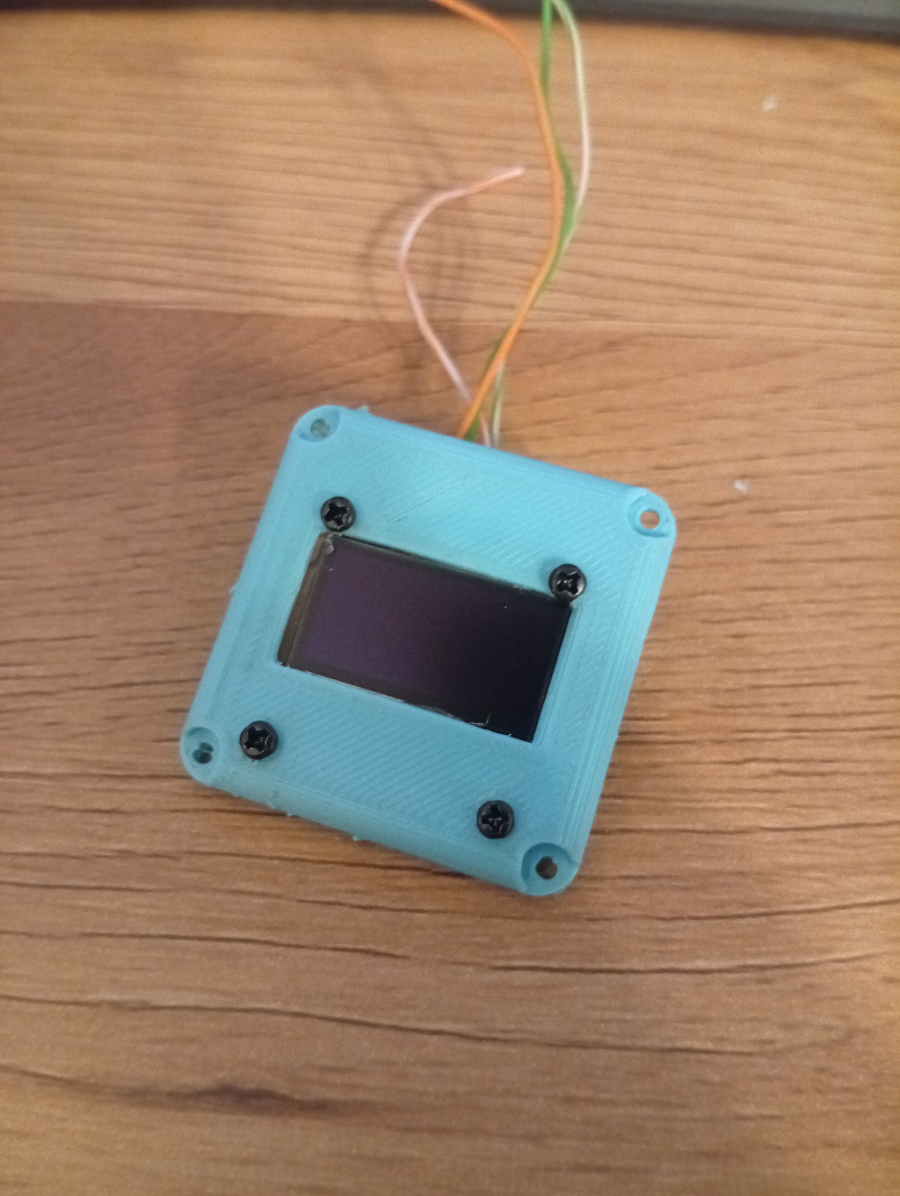
- OLED Display
Screw in the 2x2mm screws and hot glue the SSD1306 to the front part of the cube solder the 4 wires to the OLED display, make sure you have some extra length, 4-5cm should be more than enough
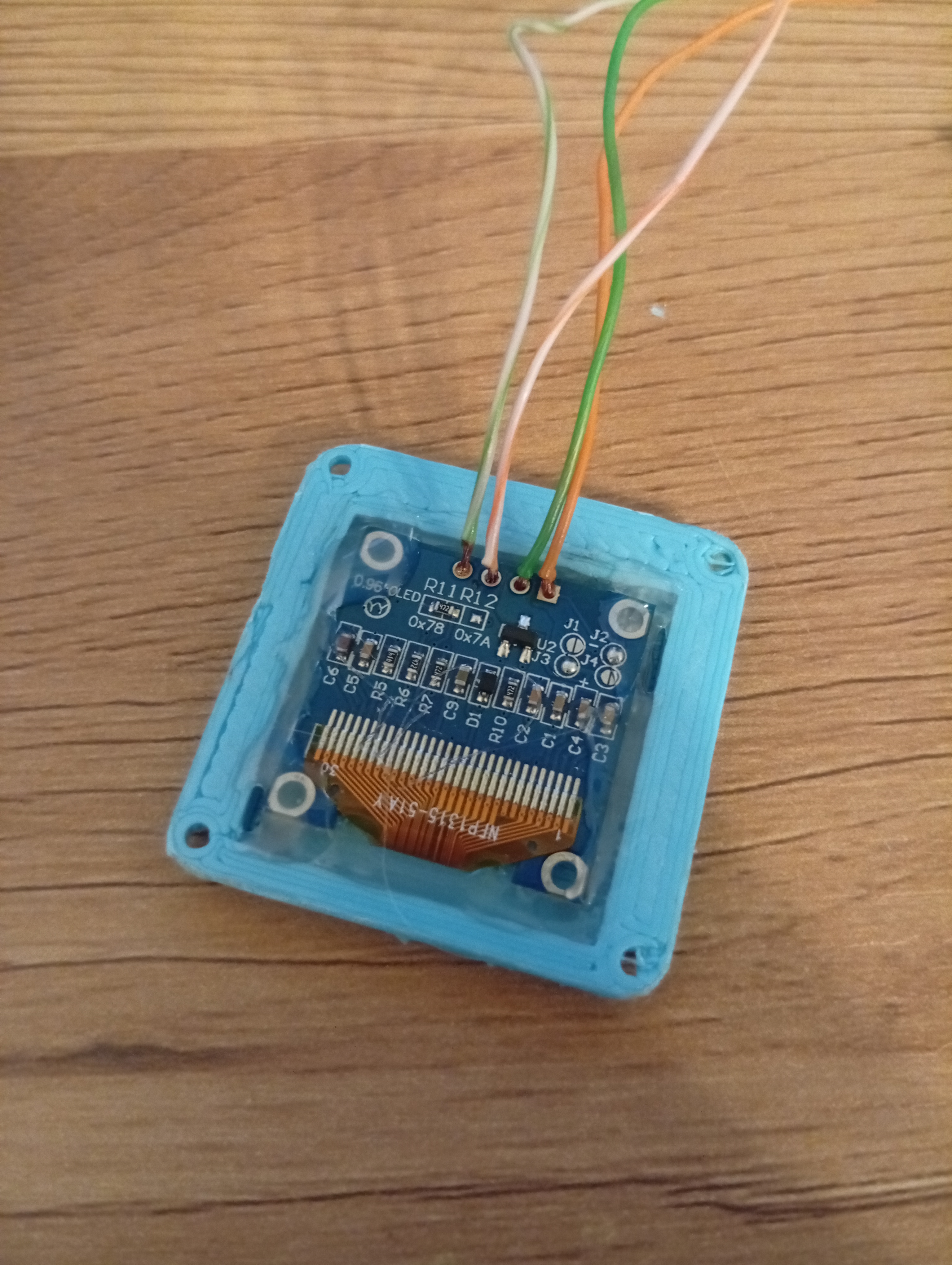
The OLED display must be connected via I2C on pins:
- SDA: D2 (GPIO4)
- SCL: D1 (GPIO5)
- GND: GND
- VCC: 3.3V pin or directly to the TP4056 output
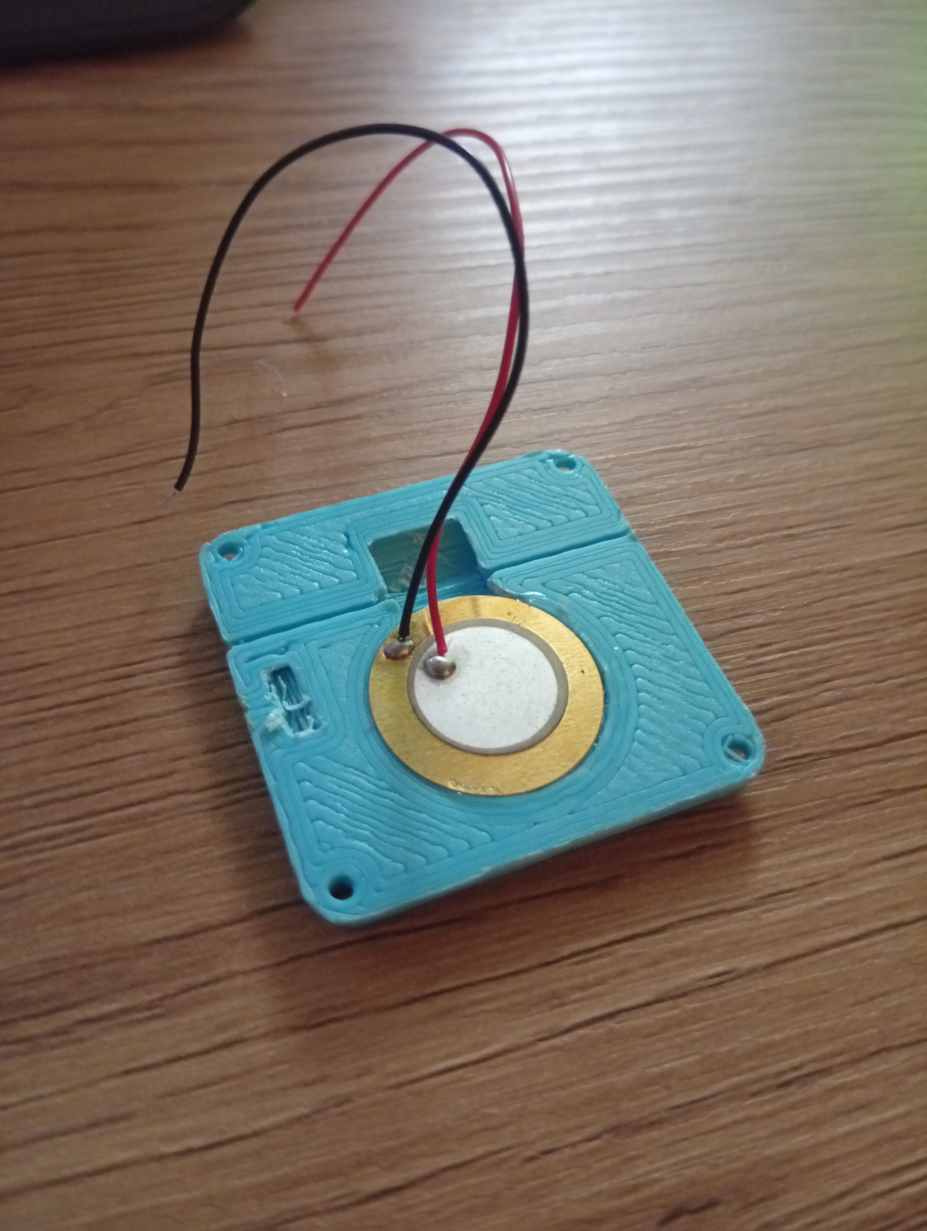
- Buzzer
Glue in the buzzer to the back part of the cube with superglue
As defined in the example config connect:
- the positive wire of the buzzer to the 3.3V
- the negative wire to PIN_BUZZER (D3) GPIO0
Battery Setup
The battery is optional. Your SmartCube will work fine without it at this point; however, adding one makes it portable (and much cuter).
A single 700 mAh 14250 battery lasts about 24 hours. Keep in mind there's currently no way to manually power the Cube off, it will continue running until the battery is depleted. The TP4056 prevents the cell from being completely drained and should protect it from damage.
-
Solder the 14250 battery to the TP4056 input pins.
-
Wire the TP4056 output to the 3.3V pin on the D1 Mini to power the device.
-
Connect the 5V output pin from the D1 Mini to the TP4056 input port to allow charging through the USB data port on the ESP8266.
-
(Optional) Add a voltage divider to monitor battery level with the ESP8266 A0 pin.
- R1 = 220kΩ (between battery positive and A0)
- R2 = 56kΩ (between A0 and GND)
This safely scales 4.2V down to ~0.85V, allowing the software to read and estimate the battery’s charge level.
Notes
- This is still a work in progress
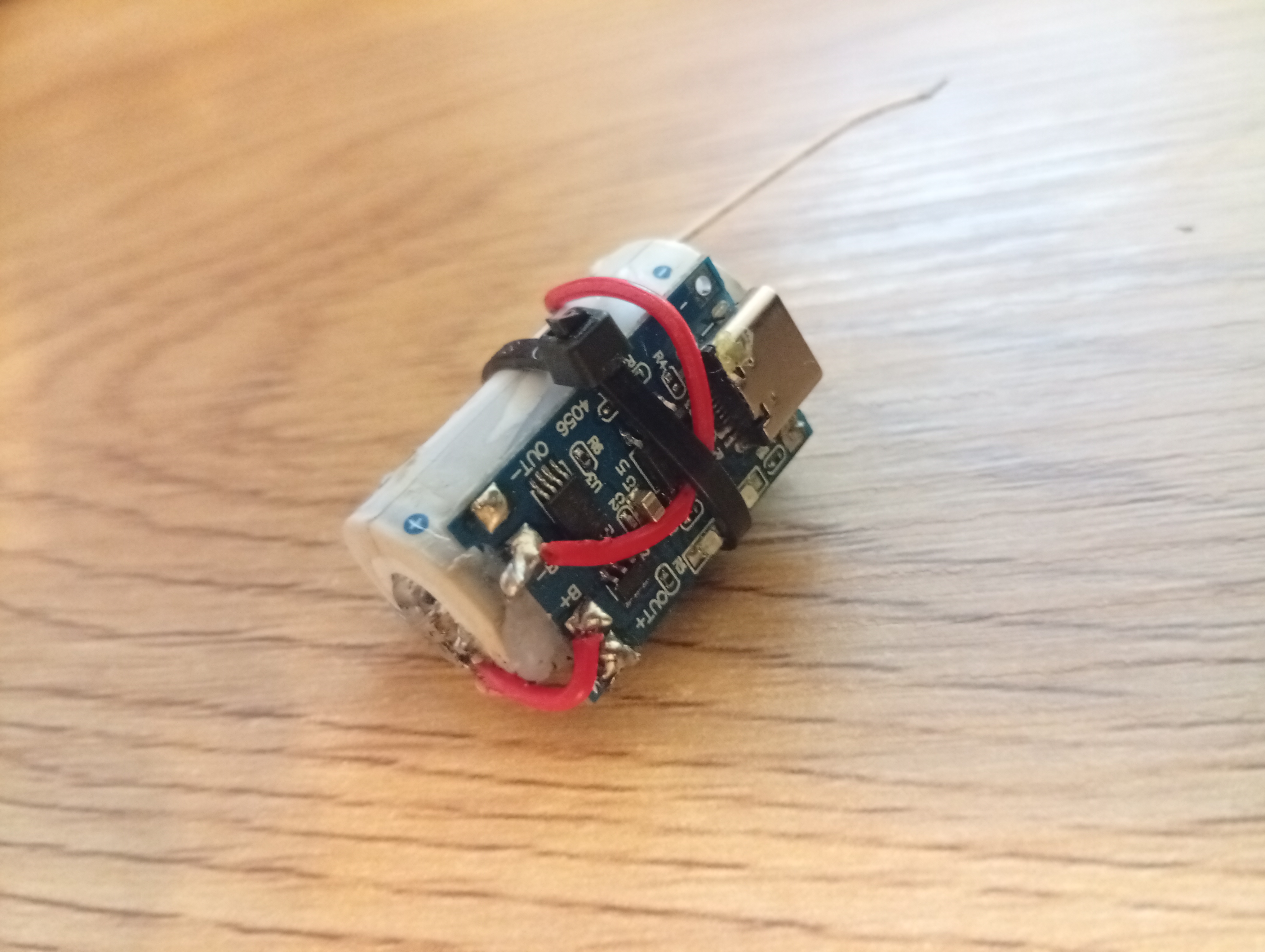
- Everything is pretty tightly packed in there and it's a mess. But it's not as hard to make as it looks.

- Ensure all connections are secure and isolated. Hot glue is your friend.
- Test the circuit thoroughly before placing and gluing it in the enclosure.
- Battery is the trickiest part to fit in, it's best to glue the charging module directly to it and put it in the case last
For questions or additional details, feel free to reach out! I would love to hear some feedback. Good luck and have fun :)